News
Sep.07, 2026
A globe-style control valve is often the best starting point for precise throttling because plug travel can create a defined flow characteristic and the trim can be engineered for the pressure drop. A characterized rotary valve may be better for high capacity or limited space. The correct answer requires sizing against the complete operating envelope.
Understanding on-off versus modulating control helps prevent an isolation valve from being misapplied in continuous throttling duty.

A throttling valve must do more than survive partially open. It must deliver the required flow at each operating point, respond to the controller, remain stable near the expected travel, and tolerate the energy released across the trim. The Fisher Control Valve Handbook treats valve sizing, installed behavior, actuator response, liquid and gas calculations, cavitation, flashing, noise, materials, and pressure-temperature ratings as connected decisions.
| Candidate | Where it often fits | Trade-off to check | Data needed before selection |
|---|---|---|---|
| Globe-style control valve | Precise or demanding modulation, engineered trim | Higher pressure loss, larger actuator force or envelope | Flow cases, pressure drop, fluid properties, characteristic, trim, actuator |
| Characterized ball valve | High capacity, rotary package, broad range in some services | Pressure recovery, noise/cavitation, seat/trim erosion, torque | Cv curve, opening angle, differential pressure, shutoff, materials |
| High-performance butterfly valve | Large sizes, compact installation, moderate control duty | Disc/shaft effects, available torque, velocity, pressure recovery | Disc style, angle, actuator torque, direction, seat and shaft data |
| Needle valve | Very low flows or fine manual adjustment | Small passages and limited capacity | Cleanliness, viscosity, required range and pressure drop |
| Gate valve | Normally full-open/full-closed isolation | Gate/seat exposure and poor control repeatability when partly open | Treat as isolation unless a qualified design says otherwise |
To separate throttling duties from isolation and backflow prevention, use this industrial valve types overview before evaluating a specific control-valve design.
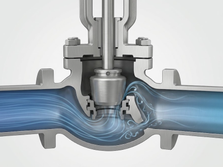
In a globe valve, the plug moves relative to the seat and changes the flow area with travel. The TLV manual-valve guide explains that globe valves can handle flow control and notes less risk of plug or seat damage during partial opening than with conventional manual ball valves. It also highlights the trade-off: the internal path can create greater pressure drop.
A control-valve body adds engineered trim, actuator, positioner, and defined performance data to that basic geometry. Equal-percentage, linear, and quick-opening characteristics describe how rated flow coefficient changes with travel under specified test conditions. The best inherent characteristic is not selected by habit; the system pressure losses and process gain determine the installed behavior.
A rotary design may reduce weight and envelope or provide higher flow capacity for a given nominal size. Characterized ball segments and high-performance butterfly bodies are established control-valve styles, not merely manual isolation valves held halfway open. They still require manufacturer data for flow coefficient, pressure recovery, dynamic torque, actuator margin, seat loading, allowable differential pressure, and noise.
Do not infer throttling suitability from a generic product-family name. KAIWEI’s live butterfly valve catalog lists concentric and offset families, while its control valve catalog lists control-oriented products. The exact trim, actuator, signal, fail position, available torque, Cv/Kv, and allowable pressure drop need confirmation for the proposed model.
For liquids, a basic non-choked sizing relationship is often introduced in the form:
Q = Cv × sqrt(ΔP / SG)
where Q is water-equivalent flow in U.S. gallons per minute under the equation’s defined unit convention, ΔP is valve pressure drop in psi, and SG is liquid specific gravity. Rearranging gives Cv = Q × sqrt(SG / ΔP).
As a simple illustration, a water-like liquid at 100 gpm with 4 psi allocated across the valve gives a preliminary Cv = 100 × sqrt(1/4) = 50. This is not a final selection. Attached reducers, viscosity, vapor pressure, critical pressure, choked flow, flashing, cavitation, gas expansion, units, safety factors, and the desired operating travel can change the result. Use the applicable sizing standard and current manufacturer coefficients.
Review Cv in valve sizing before comparing trim style, travel, and actuator requirements.
The available pressure drop across a valve must be evaluated at minimum, normal, and maximum flow.
An oversized valve may spend normal operation close to the seat, where resolution, friction, and process gain can produce cycling. An undersized valve may not pass maximum flow or may require excessive pressure drop. Build a case table before requesting a quotation:
| Case | Flow to provide | Pressures to provide | Temperature to provide | Fluid data to provide |
|---|---|---|---|---|
| Minimum stable | Minimum controllable flow and units | Inlet/outlet values and gauge-or-absolute basis | Actual minimum operating temperature | Density/SG, viscosity, vapor pressure or gas data |
| Normal | Expected continuous flow and units | Normal inlet and outlet values | Expected continuous temperature | Properties at the normal condition |
| Maximum | Maximum required flow and units | Maximum-case inlet and outlet values | Maximum operating temperature | Properties at the maximum case |
| Start-up/upset | Intermittent flow and duration | Transient inlet/outlet limits | Transient temperature limits | Phase or composition changes and associated risk |
Then specify allowable noise, shutoff class, leakage direction, rangeability, response time, fail-open/fail-closed/fail-in-place action, utility supply, control signal, hazardous-area requirement, and maintenance constraints.
Sizing the flow path does not validate the pressure boundary. ASME B16.34 covers pressure-temperature ratings, materials, dimensions, examination, testing, and marking for specified new valves. Confirm the material group and temperature before interpreting the pressure class, and state the project’s required valve/control sizing, leakage, testing, and documentation standards separately.
Send KAIWEI the operating-case table, fluid composition, pipe and line class, required body/trim/seat/packing materials, shutoff and flow direction, valve standard, end connection, actuator utilities, control signal, fail action, inspection and document requirements. The KAIWEI solutions page outlines the inquiry route, and the contact page can receive the technical request or RFQ.
Ask the response to state the calculated required Cv/Kv, selected rated coefficient and travel at each case, predicted noise or cavitation assessment where relevant, allowable differential pressure, actuator sizing basis, and assumptions. That makes the recommendation reviewable.
More News
Oct.01, 2026

Sep.30, 2026
Sep.25, 2026


