Sep.23, 2026
Cv is a flow coefficient that expresses how much water can pass through a valve at a stated pressure drop under defined reference conditions. It matters because it connects the process flow and available pressure drop to a valve’s hydraulic capacity. The required Cv must be compared with the rated Cv of the actual valve at the intended travel—not with nominal line size alone.
When comparing industrial valve products, review hydraulic capacity alongside the required function, materials, pressure-temperature rating, and actuation.
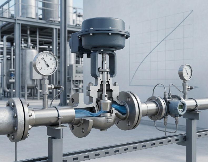
In common US customary usage, Cv is the number of US gallons per minute of water at approximately 60°F that passes through a valve with a pressure drop of 1 psi under specified conditions. The definition makes Cv a convenient comparison value, but it does not mean every service behaves like water.
Kv is a related metric coefficient based on cubic metres per hour of water and a one-bar pressure drop. Cv and Kv are convertible, but they are not numerically identical. State which coefficient and unit convention a worksheet uses so that a silent conversion error does not enter the selection.
Required Cv is calculated from flow, fluid properties, upstream and downstream conditions, and the selected sizing method. Rated Cv is supplied for a specific valve model, trim, size, flow direction, and travel. A useful review compares the required value at each operating case with the manufacturer’s curve or table.
A control valve should not merely have a maximum rated Cv above the largest calculated requirement. The normal operating point, minimum controllable flow, installed characteristic, actuator resolution, rangeability, and available system pressure drop also matter. An isolation valve may be reviewed differently, but its open-position loss still should be checked against system requirements.
KAIWEI’s control valve category is a product-family starting point, not a substitute for a model-specific Cv curve.
For a simplified turbulent, non-choked liquid case using consistent US customary units:
Q = Cv × √(ΔP / SG)
Rearranging gives:
Cv = Q × √(SG / ΔP)
If water-like liquid must flow at 100 US gpm with 4 psi available pressure drop, the preliminary required coefficient is:
Cv = 100 × √(1 / 4) = 50
This result is not a finished valve selection. It does not by itself address viscosity, piping reducers, vapor pressure, cavitation, flashing, noise, velocity, valve style, travel, actuator capacity, or safety margin. It also does not prove that a catalog valve with a nominal Cv of 50 will meet every operating case.
An undersized valve may not pass the required maximum flow even when fully open. It may also consume more pressure drop and create excessive velocity, noise, erosion, or cavitation risk depending on the service.
An oversized control valve may spend normal operation close to the seat. Small stem or shaft movements can then produce disproportionately large flow changes, reducing resolution and making the loop difficult to tune. Oversizing also does not solve an actuator-force or shutoff requirement. The valve must be sized as part of the system, not as an isolated catalog component.
For the related choice of body and trim, see which valve is best for throttling flow, which compares control duties and the operating data needed to evaluate candidate designs.
The Fisher Control Valve Handbook presents equations and application factors for liquid, gas, steam, cavitation, flashing, noise, and other sizing topics. Those methods require verified process data and the valve manufacturer’s product-specific coefficients.
For a throttling valve, rated Cv usually changes with travel. Linear, equal-percentage, quick-opening, and modified characteristics describe different relationships between travel and capacity under test conditions. The installed characteristic can differ because the system pressure distribution changes as flow changes.
Two valves of the same nominal size may have different Cv values because their ports, discs, balls, plugs, cages, seats, shafts, reducers, and body passages differ.
Provide minimum, normal, and maximum flow; upstream and downstream pressure for each case; design pressure; operating and design temperature; fluid name and composition; phase; density or specific gravity; viscosity; vapor pressure; critical pressure; molecular weight; compressibility; and ratio of specific heats when applicable.
Also provide line size and schedule, reducers and nearby fittings, allowable noise, required travel range, shutoff differential pressure, leakage requirement, flow direction, fail position, actuator utilities, materials, solids, corrosion or erosion concerns, and applicable standards. The related KAIWEI guide lists the broader information needed to size an industrial valve.
ASME B16.34 covers pressure-temperature ratings and construction subjects for valves within its scope. Those requirements and hydraulic capacity answer different questions and both may need to be satisfied.
When reviewing a proposed valve, request the calculation basis, required Cv for each case, proposed model and trim, rated Cv curve, expected travel, predicted pressure drop, velocity and cavitation checks, actuator sizing basis, pressure-temperature rating, assumptions, exclusions, and unresolved data.
Preparing a valve-sizing RFQ? Send your minimum, normal, and maximum flow cases, inlet and outlet pressures, temperature, and fluid properties to KAIWEI VALVE to discuss valve selection and request a project-specific quotation.
More News
Oct.01, 2026

Sep.30, 2026
Sep.25, 2026


