News
Oct.01, 2026
A pump runs, a process slows, and the pressure gauge downstream reads lower than expected. That difference can be normal—or a sign that a valve or another part of the system needs attention. Understanding industrial valve pressure drop causes helps operators tell the difference, protect equipment, and maintain the flow a process needs. This guide explains how to measure pressure loss across a valve, what affects it, and how to investigate it without guessing.
Upstream P1
Downstream P2
Valve
ΔP = P1 − P2
Pressure drop is the reduction in fluid pressure between two points as fluid flows through a system. Across a valve, it is commonly written as ΔP = P1 − P2, where P1 is upstream pressure and P2 is downstream pressure. Use the same pressure units for both readings, such as bar, kPa, or psi.
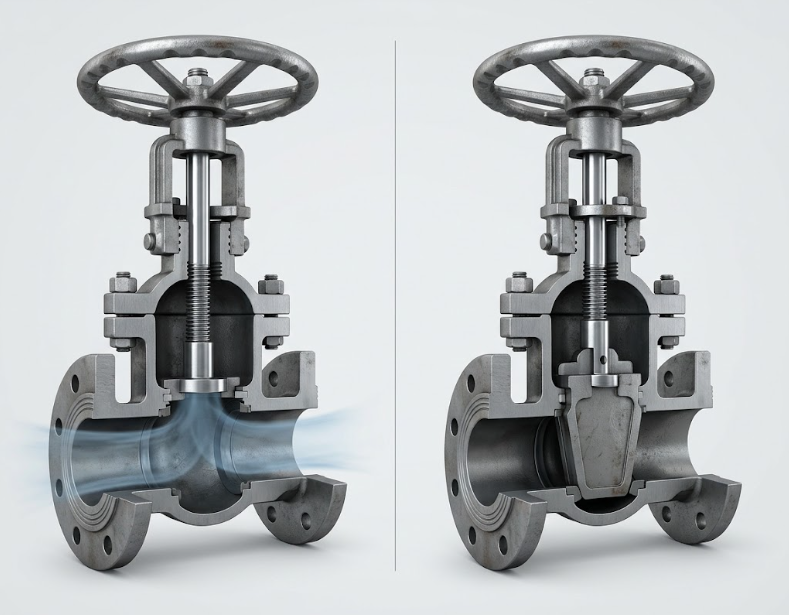
A valve changes the flow path. Its body, seat, disc, plug, and other internal parts create resistance, so some pressure energy is converted into heat, sound, and turbulence. A throttling valve creates a deliberate restriction to control flow. A fully open valve also has resistance, but the pressure loss is usually lower than when it is partly closed. The actual result depends on valve design, size, opening, fluid, and flow rate.
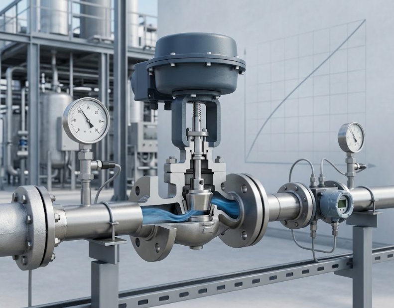
Pressure drop is not automatically a defect. Engineers often select a control valve to use a planned pressure difference to regulate flow. The concern is an unexpected or excessive drop that reduces downstream pressure, limits capacity, wastes pumping energy, or contributes to noise, vibration, cavitation, or erosion.
As a valve closes, the available flow area becomes smaller. Fluid speeds up through the restricted opening, and more pressure is converted into energy losses. This is normal for throttling service. If the valve must remain almost closed to achieve the desired flow, however, its size, trim, or control settings may not suit the operating conditions.
The flow coefficient, Cv, is a measure of a valve’s capacity. In the common U.S. definition, Cv is the number of U.S. gallons of water at 60°F that pass through a valve in one minute with a 1 psi pressure drop. For water-like, incompressible liquids in standard U.S. units, a simplified relation is Q = Cv × √(ΔP/SG), where Q is flow in gallons per minute and SG is specific gravity relative to water. Rearranged, ΔP = SG × (Q/Cv)².
Illustrative example: For water (SG ≈ 1) flowing at 100 gpm through a valve with an operating Cv of 50, the simplified estimate is ΔP = (100/50)² = 4 psi. This is an example, not a sizing recommendation. Use the manufacturer’s certified data and the applicable sizing method for the actual valve, fluid, pressure, temperature, and operating range. Gas and steam sizing require additional compressibility and pressure-ratio factors; do not apply the liquid equation to them.
For a given valve opening, a higher flow rate commonly produces a larger pressure drop. Viscosity also matters: a thick liquid may create more resistance than water, especially in small passages or at low temperatures. Changes in density, temperature, composition, or phase can alter the result. Compare actual operating conditions with the assumptions used for valve selection.
Debris, scale, corrosion products, a damaged seat, or a clogged strainer can restrict flow. Pressure loss may also occur in elbows, reducers, filters, and partially closed isolation valves near the valve. A pressure reading taken too close to a fitting or turbulent outlet may not represent stable line pressure. Check the entire section, not only the valve body.
When liquid pressure falls below its vapor pressure inside a valve, vapor bubbles can form. If pressure recovers downstream, the bubbles may collapse and cause cavitation, which can lead to noise, vibration, and surface damage. If downstream pressure stays below the liquid’s vapor pressure, some vapor may remain; this is called flashing. Both conditions need review against the fluid’s vapor pressure and the valve manufacturer’s limits. A pressure drop alone does not prove cavitation.
Pressure varies through a valve. The lowest pressure may occur inside the trim, then recover partly after the restriction. That recovered downstream pressure is not the same as the pressure at the narrowest point. Make sure the taps, gauges, and measurement locations are appropriate for the diagnostic question. Also confirm instruments are calibrated and read at the same time under steady operating conditions.
For liquid flow, the simplified Cv equation can help explain why a higher flow or smaller effective opening may increase ΔP. It is not a substitute for a full valve-sizing calculation. The and the provide further background on control-valve selection and operation. For formal sizing, consult the applicable edition of IEC 60534-2-1 / ISA 75.01.01 and the valve manufacturer’s documentation.
Lower pressure drop is not always the goal. A control valve needs enough pressure difference to control flow, and changing the valve can affect pump duty, process stability, noise, and safety. Any modification should be checked against the complete system design.
Industrial valves are used to start, stop, direct, or regulate fluids across many sectors. Pressure-drop assessment is useful anywhere flow and downstream pressure matter, including:
The right valve and measurement method depend on the service. A water-system check, for example, cannot be copied directly to a compressible gas or steam line.
Knowing the source of pressure loss helps teams distinguish normal control behavior from an equipment or system problem. It can support stable process flow, protect downstream equipment, identify restrictions, and inform valve or pump decisions. It also helps prevent unnecessary valve changes based on a single pressure reading.
Use measurements and documented operating conditions rather than claims such as “high capacity” or “low loss” without context. The relevant comparison is the actual pressure drop at the required flow and fluid conditions, checked against the project specification and manufacturer data.
Yes. Flow through a valve encounters resistance, and a throttling valve intentionally creates a pressure difference to control flow. Investigate when the measured drop is higher than the design expectation or causes a process, energy, noise, or equipment concern.
Not in every operating situation, but a valve with insufficient capacity for the required flow may need a larger pressure difference or may restrict the flow. Valve opening, trim, fluid properties, and system conditions also matter. Compare operating Cv and process data rather than nominal size alone.
For a liquid in the standard U.S. Cv convention, a common simplified relation is ΔP = SG × (Q/Cv)², with Q in gpm and ΔP in psi. This approximation has limits. Use the applicable standard and manufacturer sizing method for the service; use separate compressible-flow methods for gas and steam.
Yes. Deposits, debris, or damaged internal parts can reduce the available flow area and increase resistance. A clogged strainer or another restriction nearby can produce a similar symptom. Inspect safely and confirm the cause before replacing the valve.
Get qualified support if the line carries hazardous fluid, pressure or temperature is high, the valve shows severe vibration or noise, cavitation or flashing is suspected, or the required sizing calculation is outside your expertise. Follow site safety rules and never open equipment that has not been properly isolated and depressurized.
Start with the valve data sheet and user guide, then compare the specified operating range with verified pressure, flow, and temperature readings. If the cause remains unclear, share those records and the service conditions with a qualified valve engineer or supplier. For project-specific product information or selection support, contact KAIWEI VALVES and request documentation that matches your application. Learning how to reduce pressure drop in a valve begins with accurate measurements, correct sizing, and a safe review of the whole system.
More News

Sep.30, 2026
Sep.25, 2026
Sep.23, 2026


