Choose an industrial valve by matching its function, materials, pressure and temperature limits, flow requirements, and actuation to the actual process—not by selecting on pipe size or purchase price alone. This industrial valve selection guide covers how to choose an industrial valve, valve sizing for process applications, and the details engineers should confirm before ordering. Flow control, pressure drop, and corrosion resistance matter, as do professional terms such as Cv, NPS, and ASME pressure class. The result is a specification that fits the service and can be checked before installation.
Industrial Valve Selection: Start with the Job the Valve Must Do
A valve that works for clean water at moderate conditions may be unsuitable for abrasive slurry, steam, a corrosive chemical, or a gas line where leakage control is critical. The first question is not “Which valve is best?” It is “What must this valve do in this particular line?”
- Isolation: Stop or permit flow. A gate, ball, butterfly, or globe valve may be suitable depending on service, size, pressure, and required shutoff performance.
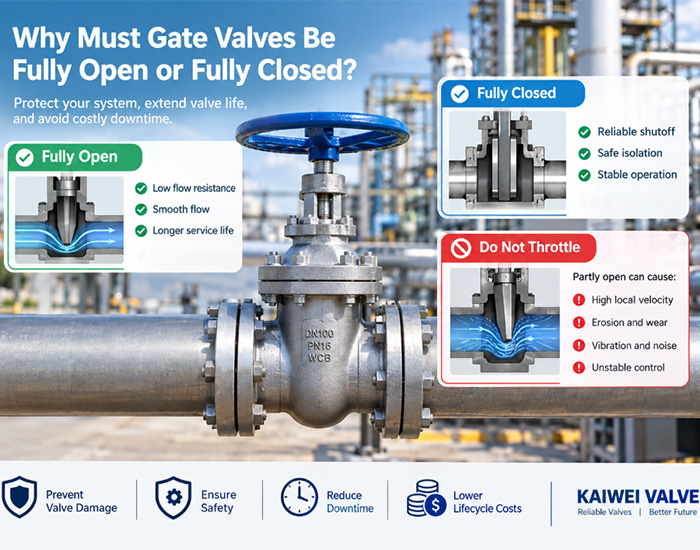
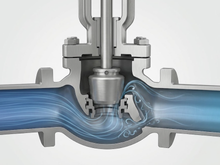
- Throttling: Regulate flow over part of the valve’s travel. Globe valves and properly engineered control valves are common options; an isolation valve is not automatically suitable for continuous throttling.
- Non-return: Limit reverse flow. A check valve is selected according to flow direction, velocity, installation position, and the risk of slam or vibration.
- Pressure protection: Relieve pressure when specified design conditions are exceeded. Relief and safety valves require a separate engineering basis and applicable code review.
Also establish what failure means for the process. Should an actuated valve fail open, fail closed, or remain in its last position? The answer depends on the hazard review and operating philosophy; it is not a supplier preference.
Industrial Valve Selection Preparation: Information, Tools, and Prerequisites
Gather process and piping information before asking for a quotation. A valve supplier cannot reliably confirm suitability from nominal pipe size alone.
Industrial Valve Selection Data Checklist
- Process fluid: Name, composition, concentration, phase, contaminants, solids, and any known toxicity or flammability hazards.
- Operating envelope: Normal, minimum, maximum, startup, shutdown, cleaning, and upset temperatures and pressures. Record design conditions separately from normal operating conditions.
- Flow information: Minimum, normal, and maximum flow; required flow direction; expected pressure drop; and whether the valve will isolate, modulate, or perform both duties.
- Pipe and connection details: NPS (nominal pipe size), piping schedule where relevant, end connection, facing, and applicable piping specification. NPS is a nominal designation, not a direct measurement of the pipe’s internal diameter.
- Operating method: Manual, pneumatic, electric, or hydraulic actuation; operating frequency; available utilities; required response; and fail position if actuated.
- Site conditions: Indoor or outdoor installation, ambient temperature, vibration, hazardous-area classification, access, and maintenance constraints.
- Required documentation: Applicable design and testing standards, material certificates, inspection requirements, traceability, and project-specific approval documents.
Useful tools include the current process flow diagram and piping and instrumentation diagram, line list, piping class, fluid-property data, valve data sheet, and the project’s applicable codes and specifications. For control-valve sizing, use the project-approved sizing method and current manufacturer data or suitable engineering software; do not estimate a final valve size from a rule of thumb.
Step-by-Step Industrial Valve Selection Guide
-
Step 1: Define the Industrial Valve Function and Safe State
Tools: Process flow diagram, P&ID, control narrative, and hazard-review documentation.
Action: Mark the valve’s location and state whether it provides isolation, throttling, non-return, pressure relief, or another defined duty. For actuated valves, record the required action on loss of power, air, or signal.
Parameters: Required operating modes, flow direction, shutoff duty, operating frequency, and fail-open, fail-closed, or fail-in-place requirement where applicable.
Check: Confirm the specified duty matches the process and control documents, and that the safe state has an engineering basis.
If it fails: If the documents conflict or the safe state is unclear, stop the selection and resolve it with the process, instrumentation, and safety teams. Do not infer a fail position from the valve type.
-
Step 2: Record the Industrial Valve Service Conditions
Tools: Line list, process data, fluid-property information, and operating history if available.
Action: List the fluid composition and the minimum, normal, and maximum conditions, including startup, shutdown, cleaning, and credible upset cases. Identify entrained solids, flashing, cavitation risk, corrosive constituents, and possible polymerization or deposits where relevant.
Parameters: Pressure, temperature, flow, fluid phase, density or specific gravity, viscosity, vapor pressure when relevant, and solids characteristics.
Check: Verify that the stated limits come from the process basis rather than a single normal operating reading. Ensure pressure and temperature are considered together when checking the valve’s rating.
If it fails: If fluid composition or upset conditions are unknown, request process-owner confirmation. A guessed fluid description can lead to unsuitable trim, seals, or body materials.
-
Step 3: Select an Industrial Valve Type for the Duty
Tools: Valve data sheets, piping class, manufacturer technical literature, and applicable project specifications.
Action: Compare suitable valve families against the job. For example, assess whether a ball or gate valve provides the required isolation, whether a globe or engineered control valve is appropriate for throttling, and whether a check-valve design suits the flow and installation.
Parameters: Required shutoff, allowable pressure loss, flow characteristic, size range, flow direction, installation orientation, and maintenance access.
Check: Confirm that the chosen design is approved for the actual service and operating mode. Review manufacturer limits for throttling, solids, velocity, and installation position rather than relying on a generic valve-type comparison.
If it fails: If more than one design appears suitable, compare documented performance and lifecycle requirements on the same basis. Ask the supplier to identify limitations and assumptions in writing.
-
Step 4: Verify Industrial Valve Materials and Sealing
Tools: Corrosion data, material specifications, fluid composition, manufacturer compatibility information, and project material requirements.
Action: Specify the body, trim, stem, seat, packing, and gasket materials as required for the service. Check wetted components and seals individually; the body alloy alone does not establish chemical compatibility.
Parameters: Chemical concentration, temperature, pressure, contaminants, erosion or abrasion exposure, and any required emissions or leakage criteria.
Check: Confirm compatibility against authoritative project or manufacturer data and verify the selected materials appear consistently in the quotation and final data sheet.
If it fails: If compatibility data are inconclusive, consult a corrosion or materials specialist and obtain written manufacturer confirmation. Do not choose a material solely because it is described as “stainless” or “chemical resistant.”
-
Step 5: Check Industrial Valve Pressure, Temperature, and Connections
Tools: Piping class, design conditions, valve standard, and supplier dimensional and rating tables.
Action: Match the valve pressure class and end connections to the piping system and the full design envelope. Confirm face-to-face dimensions, end type, facing, and installation space.
Parameters: Design pressure and temperature, ASME pressure class where specified, NPS, connection type, and applicable design standard.
Check: Verify the pressure-temperature rating for the actual material and conditions. A class designation is not a universal pressure value independent of temperature and material. Check the applicable standard and project specification rather than assuming similarly named ratings are interchangeable.
If it fails: If the valve and piping ratings or connection details differ, do not rely on adapters or a nominal size match without engineering approval. Correct the data sheet before procurement.
-
Step 6: Size the Industrial Valve for Flow
Tools: Process flow cases, fluid properties, pressure-drop basis, and an approved sizing calculation or manufacturer sizing tool.
Action: Evaluate the minimum, normal, and maximum flow cases. For liquid-flow screening in customary units, the relationship commonly written as
Q = Cv × √(ΔP/SG)links flow (Q), valve coefficient (Cv), pressure drop (ΔP), and specific gravity (SG). This simplified relationship is not a substitute for full sizing when effects such as cavitation, flashing, viscosity, or complex service matter.Parameters: Flow rate, upstream and downstream pressure, fluid properties, required pressure drop, and manufacturer-rated Cv or equivalent capacity data.
Check: Confirm that the selected valve can handle all stated cases and that a control valve has a suitable operating range and controllability under the project’s criteria. Ensure the calculation uses consistent units and the correct fluid assumptions.
If it fails: If the valve is oversized, undersized, or near a limiting condition, revisit the pressure-drop basis, valve type, trim, or system design with a qualified engineer. Do not solve a sizing mismatch by choosing a larger nominal pipe connection alone.
-
Step 7: Specify the Industrial Valve Actuator and Accessories
Tools: Control narrative, instrument and electrical specifications, actuator sizing data, and hazardous-area requirements.
Action: Select manual or powered operation as required. For actuators, define the supply, control signal, required operating time, duty cycle, position indication, solenoid or other accessories, and the required fail action.
Parameters: Required operating torque or thrust across the service envelope, supply pressure or voltage, control method, environmental rating, and any hazardous-area certification.
Check: Obtain manufacturer confirmation that actuator output covers the valve’s required operating load under the specified conditions. Verify the complete valve-and-actuator assembly, not just the actuator model number.
If it fails: If utilities, torque data, or fail action are missing, return the specification for clarification. Do not assume an actuator sized for a clean bench test will work under every process condition.
-
Step 8: Review the Industrial Valve Specification Before Purchase
Tools: Completed data sheet, quotation, approved standards list, and quality documentation requirements.
Action: Compare the offered valve line by line with the requested duty, materials, ratings, dimensions, actuation, testing, and documentation. Record deviations and obtain approval before placing the order.
Parameters: Valve type, size, pressure class, materials, end connections, trim, seat and packing, actuator, accessories, inspection, testing, and delivery documentation.
Check: Confirm that the manufacturer, model, and revision are clear and that any claimed compliance identifies the applicable standard and scope. Standards such as ASME B16.34 and ISO 5208 may be relevant depending on valve type, project requirements, and jurisdiction; confirm applicability rather than listing standards as decoration.
If it fails: Resolve every technical deviation in writing. If you are requesting a quotation from 凯维 or another supplier, send the completed service data and ask the supplier to identify assumptions, exclusions, and any conditions that limit the proposed valve.
-
Step 9: Confirm Industrial Valve Installation and Commissioning Checks
Tools: Approved installation instructions, piping drawings, inspection records, and commissioning procedure.
Action: Check flow direction, orientation, support, access, actuator clearance, cleanliness, and any installation-specific requirements. Follow the manufacturer’s instructions and the site’s approved pressure-testing and commissioning procedures.
Parameters: Flow arrow where applicable, installation position, bolting and gasket requirements, actuator settings, and approved test limits.
Check: Verify the installed tag and model against the approved documents, inspect for damage or contamination, and record functional and leak-test results as required by the project.
If it fails: Do not force a valve that binds, leaks, or fails its functional check. Isolate the equipment according to site procedures and investigate installation, contamination, adjustment, or product issues before returning it to service.
Industrial Valve Selection Case: A Documented Failure and Its Lesson
A real, publicly documented example of why operating conditions and failure modes matter comes from the Deepwater Horizon disaster. The U.S. National Commission on the BP Deepwater Horizon Oil Spill and Offshore Drilling reported that the blowout preventer did not seal the well as intended. The investigation discussed drill pipe buckling under the conditions in the well and the pipe’s position in relation to the blind shear ram. A blowout preventer is specialized well-control equipment, not an ordinary process-line valve, so this is not a customer valve-selection testimonial. It is a documented equipment case with a relevant engineering lesson: evaluate the full operating scenario and credible failure modes, not only the equipment’s nominal function. The Commission’s report is titled Deep Water: The Gulf Oil Disaster and the Future of Offshore Drilling.
For an industrial valve project, apply that lesson by checking the full pressure and temperature envelope, actuation and fail-state requirements, materials, sizing assumptions, and installation constraints. A specification that says only “isolation valve” does not describe what happens during an upset or loss of utilities.
Common Industrial Valve Selection Errors and How to Fix Them
- Choosing by line size alone: NPS identifies a nominal pipe size, not the required valve capacity. Fix: Size for the actual flow cases and check connections separately.
- Using a shutoff valve for continuous throttling: A valve designed primarily for isolation may not provide the required control or withstand the duty. Fix: State the control requirement and review the manufacturer’s operating limits.
- Checking pressure but overlooking temperature: Pressure ratings depend on material and temperature. Fix: Verify the pressure-temperature rating for the selected material and applicable standard.
- Specifying body material but not trim or seals: Seats, packing, and wetted internal parts also contact the process. Fix: List the material requirements for all relevant components and verify compatibility.
- Ignoring minimum-flow operation: A valve selected only at maximum flow may perform poorly at normal or low flow. Fix: Include the complete operating range in sizing and controllability checks.
- Leaving actuator behavior vague: “Automatic” does not define the power source, response, or safe state. Fix: Specify utilities, control method, required output, accessories, and fail action.
- Treating a standard as a complete specification: Citing a standard does not choose the valve type, materials, size, or operating duty. Fix: Use standards alongside a complete, service-specific data sheet.
- Accepting undocumented substitutions: A similar-looking product may differ in materials, ratings, dimensions, or testing. Fix: Review deviations and obtain engineering approval before purchase or installation.
Industrial Valve Selection Summary and Practical Recommendations
The right industrial valve is the one whose function, construction, materials, capacity, pressure-temperature rating, connections, and actuation meet the documented process requirements. Start with the P&ID and service data, compare all operating cases, size with an approved method, verify the complete assembly, and review the supplier’s exceptions before ordering. Keep calculations and approvals with the final data sheet so installation and maintenance teams can work from the same requirements. A clear industrial valve selection guide should make the duty, limits, and assumptions visible; for valve sizing for process applications, confirm Cv and pressure drop with the applicable engineering method; and use corrosion resistance, NPS, and ASME pressure class only in the context of the specified service.