Oct.22, 2026
The main difference between a rising stem and a non-rising stem gate valve is how the stem moves during operation. A rising stem gate valve has a stem that moves upward as the valve opens, providing a visible indication of valve position but requiring additional overhead clearance. A non-rising stem gate valve keeps the stem at a relatively fixed external height, making it suitable for installations where vertical space is limited. The right choice depends on installation space, position monitoring, fluid conditions, and maintenance requirements.
Rising stem gate valves: Provide visible stem movement and generally allow easier access to external stem threads on applicable designs.
Non-rising stem gate valves: Offer a more compact external profile and are often suitable for buried water lines and restricted installations.
Installation space: Rising stem designs need clearance above the valve; non-rising stem designs reduce this requirement.
Maintenance: Thread location and exposure to the process medium affect inspection, lubrication, and material selection.
Selection: Check the fluid, pressure, temperature, operating frequency, position indication, and project specifications before choosing either design.
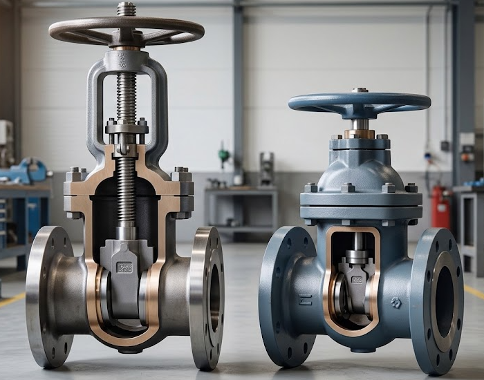
A rising stem gate valve is a gate valve in which the stem moves vertically as the valve opens and closes. In many designs, the stem is connected to the gate, while a rotating stem nut converts handwheel rotation into linear movement.
As the valve opens, the stem rises above the bonnet or operating yoke. When the valve closes, the stem moves downward. This visible movement helps operators identify the valve's approximate operating position without relying solely on the handwheel.
Many rising stem industrial gate valves use an Outside Screw and Yoke (OS&Y) arrangement. In this configuration, the stem threads are located outside the main pressure-containing body, which can make them easier to inspect and lubricate.
Visible position indication: Stem travel provides a useful visual reference for operators.
Accessible stem threads: External threads on OS&Y designs are generally easier to inspect and maintain.
Reduced contact between external threads and process fluid: This can be beneficial when the medium could affect exposed thread materials, although the stem and packing still require appropriate material selection.
Convenient above-ground operation: The design is often practical in industrial plants where operators need to check valve position and access the operating mechanism.
The main limitation is installation height. The rising stem needs sufficient clearance throughout its full travel, which may restrict its use in valve pits, compact enclosures, or other installations with limited overhead space.
A non-rising stem gate valve uses a stem that rotates without significant vertical movement outside the valve. The stem's threaded engagement moves the gate up or down internally while keeping the external valve height relatively constant.
This design is commonly selected for municipal water distribution, underground pipelines, and installations where an extending stem would interfere with surrounding structures.
The term non-rising stem describes the stem's external movement, not the gate's movement. The gate still travels internally to open or close the flow passage.
Compact vertical profile: The stem does not extend upward in the same way as a rising stem design.
Flexible installation: The lower external profile can simplify installation in valve boxes, pits, and restricted spaces.
Reduced exposure to external damage: The stem is less exposed to accidental impact from nearby equipment or personnel.
Practical for buried services: The design can suit underground water networks when paired with the appropriate body, coating, seat, and operating accessories.
One important consideration is that the stem's internal threaded arrangement may be exposed to the process medium, depending on the design. Corrosion, deposits, and fluid compatibility therefore need careful review. A non-rising stem valve may also require an indicator or another verification method when operators cannot directly observe stem travel.
Although both designs serve the same basic isolation function, their operating mechanisms affect installation, maintenance, and monitoring.
| Comparison factor | Rising Stem Gate Valve | Non-Rising Stem Gate Valve |
|---|---|---|
| External stem movement | Moves vertically during operation | Generally rotates without vertical extension |
| Visible position indication | Stem travel provides a visual reference | May require a separate indicator or verification method |
| Vertical clearance | More clearance is required | Lower external profile |
| Stem thread location | External on common OS&Y designs | Commonly internal to the valve body or bonnet arrangement |
| Thread exposure | External threads are generally accessible | Internal threads may contact the process medium |
| Maintenance access | External thread inspection is often easier | Internal stem components may require more involved access |
| Typical installation | Above-ground industrial piping | Buried water lines and space-restricted installations |
| Key selection concern | Headroom and protection of exposed components | Fluid compatibility, internal thread condition, and position verification |
These are general design characteristics. Exact construction, thread location, position indication, and maintenance procedures vary by manufacturer and model. Review the product drawing and datasheet before finalizing a specification.
Neither stem arrangement is automatically better for every pipeline. The best option depends on how the valve will be installed, operated, inspected, and maintained.
Operators need a visible indication of stem travel.
The installation provides sufficient overhead clearance.
Frequent inspection of the operating mechanism is expected.
The valve is installed in an accessible industrial plant or process area.
An OS&Y configuration is required by the project specification.
These conditions commonly arise in above-ground industrial piping, utility systems, and selected fire protection or process isolation applications. Always confirm the required valve construction against the applicable project standard and local code.
Vertical clearance is restricted.
The valve is installed in an underground pipeline or valve box.
A compact external profile simplifies installation or operation.
The selected design is compatible with the medium and maintenance arrangements.
A suitable valve-position verification method is available where required.
For buried water services, the full installation arrangement matters. Check the operating nut, extension spindle, protective cap, valve box, coating, and access provisions alongside the valve itself.
Measure the clearance above the valve, including the maximum stem extension, handwheel or gearbox, actuator, and space needed for maintenance. Do not assess clearance from the closed-valve dimensions alone.
If operators must confirm the valve position from a distance, a rising stem can provide a useful visual reference. A non-rising stem design may need a position indicator or another specified means of verification.
Stem position should not be treated as proof of seat tightness. When isolation is safety-critical, follow the site's isolation procedure and required verification method.
Review the medium's composition, temperature, pressure, solids content, and corrosive properties. For a non-rising design, pay particular attention to internal stem threads and their compatibility with the fluid. For a rising stem design, evaluate exposed threads, stem material, packing, and environmental protection.
Consider how often the valve will operate and whether technicians can safely reach the stem, bonnet, and operating mechanism. Accessible external threads can simplify certain maintenance tasks, but service life depends on materials, sealing arrangements, lubrication, installation, and operating conditions.
Confirm the required design standard, pressure-temperature rating, body and trim materials, end connections, inspection requirements, and testing documentation. For industrial steel gate valves, API 600 may be relevant when specified by the project. Waterworks valves may follow different product and installation standards.
The applicable standard must match the actual valve design, size, pressure class, material, and intended service. Do not assume that choosing a particular stem arrangement automatically establishes compliance.
When requesting a quotation, provide enough information for the supplier to assess the complete valve configuration rather than specifying only rising or non-rising stem.
Include the following details:
Nominal valve size and piping connection.
Design and operating pressure and temperature.
Fluid composition and relevant corrosion or solids concerns.
Required stem arrangement and position indication.
Body, stem, gate, seat, and packing material requirements.
Manual handwheel, gearbox, or actuator requirements.
Installation location, available clearance, and maintenance access.
Applicable design, testing, inspection, and documentation standards.
For general valve operating principles and additional design considerations, read What Is a Gate Valve and How Does It Work?.
Selecting between a rising stem and a non-rising stem gate valve starts with the installation and operating requirements. A rising stem design can support visible position monitoring and convenient external thread access, while a non-rising stem design can help reduce vertical clearance requirements.
KAIWEI VALVE supplies industrial valve solutions for applications across oil and gas, petrochemical, chemical processing, power, and other industrial sectors. Explore our industrial valve product range and share your operating conditions, installation dimensions, material requirements, and project standards when requesting a quotation.
The final recommendation should be confirmed against the specific model, technical datasheet, and service conditions.
A rising stem moves vertically as the valve opens or closes, while a non-rising stem generally rotates without extending vertically outside the valve. This affects position indication, installation clearance, and maintenance access.
A non-rising stem gate valve is often a practical choice for underground water lines because it has a lower external profile. The valve must still be suitable for the fluid, burial conditions, operating method, and required position indication.
Stem travel provides a visible indication of operating position on conventional rising stem designs. However, stem position alone does not confirm that the valve has achieved the required sealing performance.
Maintenance can be more involved when stem threads and moving components are located inside the valve. Actual maintenance requirements depend on the design, medium, accessibility, and manufacturer instructions.
OS&Y means Outside Screw and Yoke and describes a common rising stem arrangement in which the operating stem threads are outside the main valve body. Not every rising stem design necessarily uses the same OS&Y construction.
It can be used if the installation provides enough clearance for the full stem travel and safe operation. If overhead space is restricted, a non-rising stem design or another suitable configuration may be more practical.
More News
Oct.09, 2026


